A stopwatch app on a phone tells you a lap number. A GPS lap timer wired into a Haltech ECU tells you where on the track you lost the time — because the speed, RPM, boost and throttle traces are all logged against the same GPS position and timestamp. Instead of running a separate lap timer with its own screen and its own log file, wire the GPS module into the Haltech CAN bus so lap beacon, speed and position data land in the same log as every other engine channel.
- A Haltech GPS lap timer setup runs through a CAN-based GPS module wired into the ECU's CAN bus, not a standalone unit.
- ECU Manager software handles CAN configuration, channel mapping and logging rate — no extra dash or logger required for basic lap timing.
- Antenna placement is the most common failure point: a GPS module under a dash or roll cage bar will not hold satellite lock.
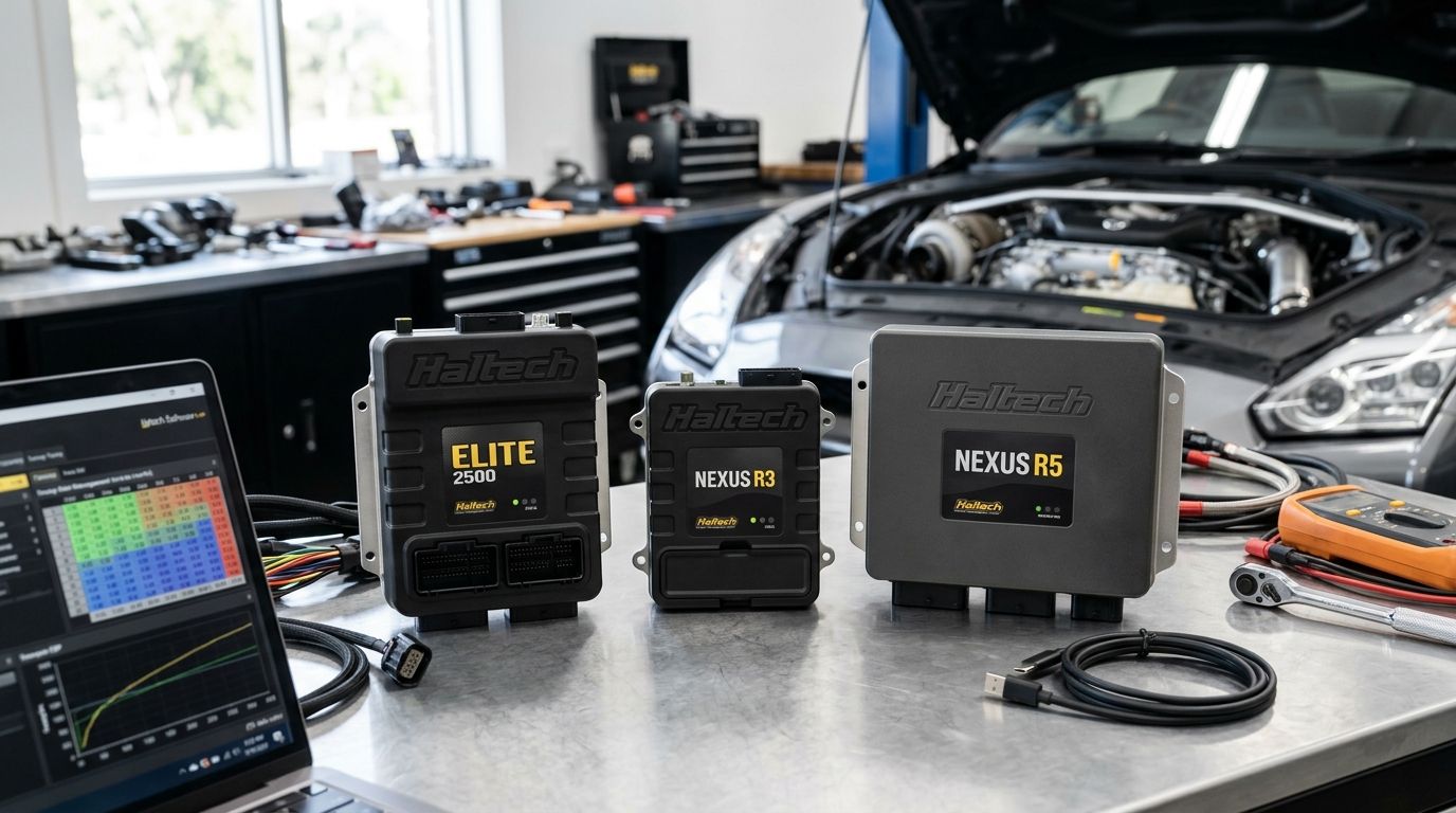
- Elite and Nexus series Haltech ECUs support CAN GPS input; older Platinum Sport ECUs need to be checked for CAN bus capacity first.
- Pairing the GPS feed with a Haltech iC-7 dash gives on-dash lap times without running a second logging device.
Why this matters
Engine data on its own tells you what the engine did. GPS data tells you where it did it. Overlaying throttle position, boost pressure and knock retard against a GPS track map turns a flat log file into a corner-by-corner diagnostic tool — useful for tuning a Haltech ECU on-track, not just on the dyno.
Most Haltech installs already have a CAN bus running to a dash or wideband controller, which means adding a GPS module is a wiring and configuration job, not a hardware overhaul. The Haltech ECU tuning side of a build benefits directly — you can correlate a lean spike or knock event with the exact corner it happened in, rather than guessing from a log timestamp.
Before you start
- A Haltech ECU with spare CAN bus capacity — Elite and Nexus series ECUs handle CAN GPS input natively through ECU Manager; confirm firmware is current before wiring anything in.
- A CAN-compatible GPS module with a clear line to open sky for the antenna — GPS chipsets need consistent satellite coverage to output usable speed and position data at racetrack update rates.
- The gotcha: mounting the antenna inside the cabin, under a dash pad, or behind a roll cage bar will pass a bench test in the shed and then drop lock on the first fast lap once the car is under a grandstand roof or tree line. Mount it with a clear view up, not just a working view in the workshop.
Wire the GPS module into the CAN bus
- Identify a spare CAN H/CAN L pair on the Haltech ECU harness or an existing CAN bus junction already feeding a dash or wideband controller.
- Connect the GPS module's CAN H and CAN L leads to the bus, keeping polarity consistent with every other CAN device already on the network.
- Confirm bus termination — a 120-ohm resistor should sit at each physical end of the CAN bus, not at every device. Adding a third termination point is the fastest way to get intermittent CAN errors.
- Run power and ground to the GPS module from a switched ignition source, not directly off the battery, so the module powers down with the rest of the electronics.
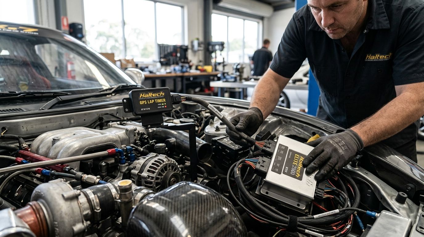
- Mount the antenna with an unobstructed view of the sky — roof, boot lid or rear deck, away from carbon fibre panels which attenuate GPS signal.
Expected result: the GPS module powers on with ignition and shows a solid lock indicator (check the module's own LED or status output) within 30-60 seconds of a clear-sky start.
Configure the CAN GPS input in ECU Manager
- Open ECU Manager and connect to the ECU with the ignition on.
- Go to the CAN Setup menu and add a new CAN device, selecting the GPS module's protocol from the preset device list if it's a recognised template, or building a custom frame if not.
- Assign incoming channels — ground speed, latitude, longitude and satellite count are the standard set most GPS lap timing setups need.
- Save the CAN device configuration and confirm live data is streaming by checking the Runtime Values window for the newly assigned GPS channels.
- Set the CAN bus baud rate to match the GPS module's specification exactly — a mismatch here is the single most common cause of a device that shows in the bus scan but never streams data.
Expected result: ground speed and satellite count update live in ECU Manager's runtime window as soon as the car moves, matching the GPS module's own display if it has one.
Map GPS channels to the logging configuration
- Open the Logging Setup menu inside ECU Manager.
- Add the GPS channels — speed, latitude, longitude and lap beacon status if the module supports one — to the active logging channel list alongside engine parameters.
- Set the logging rate to match the GPS module's update rate. A 10Hz GPS module logged at 100Hz just repeats the same coordinate ten times over; match the rate or the log file bloats for no gain in resolution.
- Run a short test lap or drive and pull the log file to confirm GPS position tracks correctly against a known road or track layout.
Expected result: a downloaded log file shows a continuous GPS trace overlaying the engine data, with speed values matching what the car was actually doing.
Send lap data to a Haltech iC-7 dash instead of a standalone timer
If the car already runs, or will run, a Haltech iC-7 dash, the same CAN-based GPS feed can drive on-dash lap timing without a second logging device competing for dash real estate. Configure the GPS module exactly as above, then in ECU Manager map the lap beacon and current lap time channels to the iC-7's display pages instead of (or alongside) a separate lap timer screen. This suits a car running both track days and street use, where one dash handles engine vitals and lap data without extra wiring for a second unit.
Troubleshooting
- GPS module shows on the CAN bus scan but no data streams — baud rate mismatch between the ECU and the module. Check the module's specification sheet against the CAN Setup baud rate field.
- Speed reads correctly stationary in the shed but drops out on track — antenna line-of-sight is being blocked by a roll cage bar, roof structure, or carbon panel. Relocate the antenna, don't just add a booster.
- Lap beacon never triggers a new lap — the beacon channel isn't mapped in the logging configuration, or the track map/start-finish coordinate hasn't been set correctly in the module.
- Log file position trace is jagged or jumps between points — GPS update rate is too low for the corner speeds being logged. A module below 10Hz update rate produces a visibly stepped trace at circuit speeds; a higher-rate module smooths this out.
- CAN bus throws intermittent errors after adding the GPS module — check termination resistor count first; a third 120-ohm resistor added somewhere mid-bus is the most common cause.
Get your Haltech CAN setup checked
Talk through GPS module wiring and CAN configuration before you're stuck at the track.
Customise your workflow
Once GPS speed and lap beacon data are logging cleanly, the same CAN bus setup carries more than just lap timing. A closed-loop fuel tuning setup using a Haltech WBC1 runs on the same CAN bus principle — one device, one configuration process, one set of channels landing in the same log file. Builders running both wideband closed-loop control and GPS lap timing on one Haltech ECU are logging fuel correction and corner position side by side, which is a genuinely useful diagnostic combination for track tuning sessions through 2026.
From there, add boost pressure, knock retard and gear position to the same logging configuration so a single log file from one track session tells the full story — engine, driver and track — instead of stitching together data from three separate devices after the fact.
FAQ
What is the best way to connect a GPS lap timer to a Haltech ECU?
Wire a CAN-based GPS module into the ECU's existing CAN bus rather than running a standalone lap timer. This puts speed, position and lap beacon data into the same log file as engine channels through ECU Manager software.
Can any GPS lap timer work with a Haltech ECU?
Only GPS modules with CAN bus output or a protocol ECU Manager can be configured to read will integrate directly. A standalone lap timer with no CAN output can still be used, but it logs separately from the ECU.
Does a Haltech GPS lap timer setup need a track map loaded?
Lap beacon triggering needs a start-finish coordinate set, either through the GPS module's own configuration or through ECU Manager depending on the module. Without it, the system logs speed and position but won't split laps automatically.
What GPS update rate is needed for accurate lap timing?
Higher update rates produce a smoother speed and position trace at circuit speeds. A low-rate module still times laps correctly but shows a visibly stepped trace when the log is reviewed corner by corner.
Can a Haltech iC-7 dash show lap times without a separate GPS lap timer?
Yes. The same CAN GPS module wired for logging can feed lap time and lap beacon data directly to iC-7 dash pages, removing the need for a second standalone timer unit.
Will adding a GPS module affect Haltech ECU tuning?
No, the GPS module is a logging input, not a tuning input. It doesn't change fuel or ignition tables, it only adds channels to the data being recorded during a tune or track session.
Why does the GPS module lose signal only at the track and not in the workshop?
Grandstands, tree lines and track infrastructure block signal that an open car park doesn't. Antenna placement that works in the shed can still fail at a circuit with more overhead obstruction.
One last thing
The most overlooked step in a Haltech GPS lap timer setup isn't the wiring, it's the logging rate mismatch — a GPS module logged at a rate far higher than its actual update rate just repeats stale coordinates and inflates the log file without adding resolution. Match the logging rate to the module's real output rate first, then worry about antenna position and CAN configuration.