Wheel spin off the throttle costs lap time and chews rear tyres, and pulling ignition timing by feel from the driver's seat doesn't scale past a track day. Configure traction control on a Haltech Elite ECU so the ECU compares driven and non-driven wheel speed in real time and cuts power automatically the moment slip exceeds your target, without you touching the throttle.
- Haltech traction control setup needs four wheel speed inputs (or two on an open diff) wired to spare digital inputs on the ECU.
- Ignition cut, ignition retard, fuel cut and drive-by-wire throttle closure are the four cut methods available in Haltech ESP software in 2026.
- Tone ring tooth count must match the software configuration exactly or slip calculations will be wrong from the first drive.
- A crank trigger kit and correctly wired wheel speed sensors are prerequisites, not optional extras, for reliable traction control.
- Start with a conservative slip target and low cut aggression, then tune up from logged data, not guesswork.
Why this matters
A driver managing wheel spin manually is reacting after the fact, and by the time the car steps out the ECU could already have pulled the timing that stops it. Traction control on a Haltech Elite ECU runs a closed loop between wheel speed sensors and a cut strategy, checking slip many times a second and intervening before the driver feels the car move.
This matters most on cars making more torque than the rear tyres can put down cleanly out of a corner or off the line: turbocharged six-cylinder swaps, big-inch LS builds, anything running forced induction on a stroker bottom end. The haltech traction control setup described here applies to any Haltech Elite ECU platform, from a Barra straight-six to an RB30 stroker, and the same logic underpins the Haltech ECU tuning guide for performance workshops.
Before you start
- Haltech Elite ECU with ESP software installed, plus a laptop with the correct USB or CAN connection to the vehicle for live configuration and datalogging.
- Four wheel speed sensor inputs (two non-driven, two driven) if you want accurate open-diff slip detection, or two inputs minimum on a locked/limited-slip rear if budget or wiring space is tight.
- A confirmed tone ring tooth count for every sensor location — the one gotcha that catches people out mid-setup. Mismatched tooth counts between the physical tone ring and the software configuration will produce a slip figure that looks plausible but is wrong, and the ECU will cut power at the wrong moment or not at all.
If the car doesn't already have a Haltech-compatible crank trigger and cam sync sensor fitted, sort that first — the crank trigger kit guide for a Haltech ECU install covers sensor gap and trigger wheel selection before you get anywhere near traction control.
Set up your wheel speed inputs
- In the ECU wiring loom, connect the front (non-driven) wheel speed sensors to two spare Digital Inputs (DI) — note the DI numbers for each side.
- Connect the rear (driven) wheel speed sensors to two further Digital Inputs, keeping left/right consistent with the front pair.
- In Haltech ESP, open ECU Operations > Wheel Speed and assign each DI to its physical location: Front Left, Front Right, Rear Left, Rear Right.
- Enter the Tone Ring Teeth value for each sensor location, matching the physical tone ring exactly.
- Enter tyre rolling circumference or wheel diameter and tyre profile so the ECU converts pulses into a real road speed for each corner.
Expected result: with the car on a hoist or rollers, the live wheel speed channels in ESP should read a sensible, matching value on all four corners as the wheels are spun by hand — if one corner reads double or half the others, the tooth count on that input is wrong.
Configure the traction control function block
- Navigate to Functions > Traction Control and set the block to Enabled.
- Set the Enable Condition — typically a switched input or a minimum vehicle speed, so the system only arms once the car is moving and doesn't interfere with idle or stationary revving.
- Build the Slip Target Table, referenced against RPM or throttle position, so the ECU knows how much difference between driven and non-driven wheel speed is acceptable before it intervenes.
- Set the Cut Method: Ignition Cut for a hard, immediate response, Ignition Retard for a smoother pull of power, Fuel Cut as an alternative or backup method, or Drive by Wire throttle closure on cars fitted with an electronic throttle body.
- Configure the Cut Aggression table so the strength of the intervention scales with how far slip has exceeded target, rather than applying one fixed cut regardless of severity.
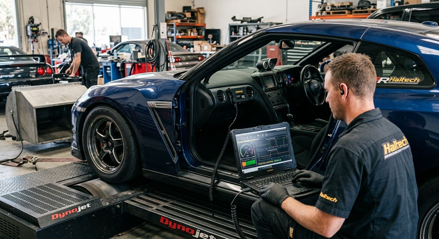
Expected result: on a rolling road or closed circuit, inducing wheel spin at part throttle should trigger a visible ignition retard or cut event in the ESP log, and the wheel speed delta should close back toward the slip target within a second or two.
Set up launch-specific wheel spin control
Standing-start wheel spin needs a more aggressive, separate strategy from mid-corner traction control, and Haltech Elite ECUs support this as a second variant of the same wheel speed setup.
- Add a second Enable Condition for launch control, typically triggered by a clutch switch or brake pressure switch combined with a low road speed threshold.
- Build a Launch Slip Target Table that allows more initial wheel speed differential than the rolling traction control table, since some controlled slip at launch is normal and desirable for a clean start.
- Set a Cut Method for launch — many setups use Ignition Cut here for a harder, more predictable response than retard alone.
- Confirm the launch strategy hands off cleanly to the rolling traction control table once road speed exceeds the launch threshold, so the car isn't running two conflicting slip targets at once.
Done this way, one wheel speed sensor setup covers both the standing start and the mid-corner cut, instead of wiring a separate system for each. For monitoring both in real time from the driver's seat, the Haltech iC-7 dash for track day and street builds can display live slip percentage and active cut status on a dedicated page.
Sourcing a Haltech ECU for the build
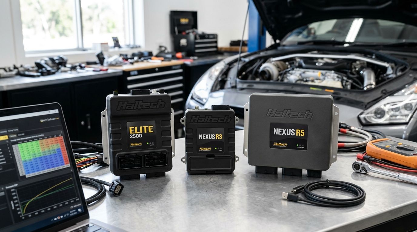
Compare Haltech Elite models before wiring in traction control.
Troubleshooting
- Traction control cuts on smooth, dry tarmac with no visible wheel spin. Check tone ring tooth count against the physical trigger wheel first — a mismatched value inflates apparent slip and triggers false cuts.
- No traction control activity at all, even with obvious wheel spin. Confirm the Enable Condition is actually being met — a switched input left in the wrong state or a vehicle speed threshold set too high will keep the function block dormant.
- Cut feels too harsh and unsettles the car mid-corner. Reduce Cut Aggression at low slip values so the first stage of intervention is gentle, reserving a hard ignition cut for larger slip events only.
- Wheel speed reads erratic or jumps between corners. Inspect sensor air gap and mounting — a loose sensor or damaged tone ring produces noisy pulses that the ECU reads as sudden slip spikes.
- Rolling traction control and launch control fight each other at the handoff speed. Check the road speed threshold that separates the two tables and widen the gap slightly so one strategy is fully disengaged before the other engages.
Customise your workflow
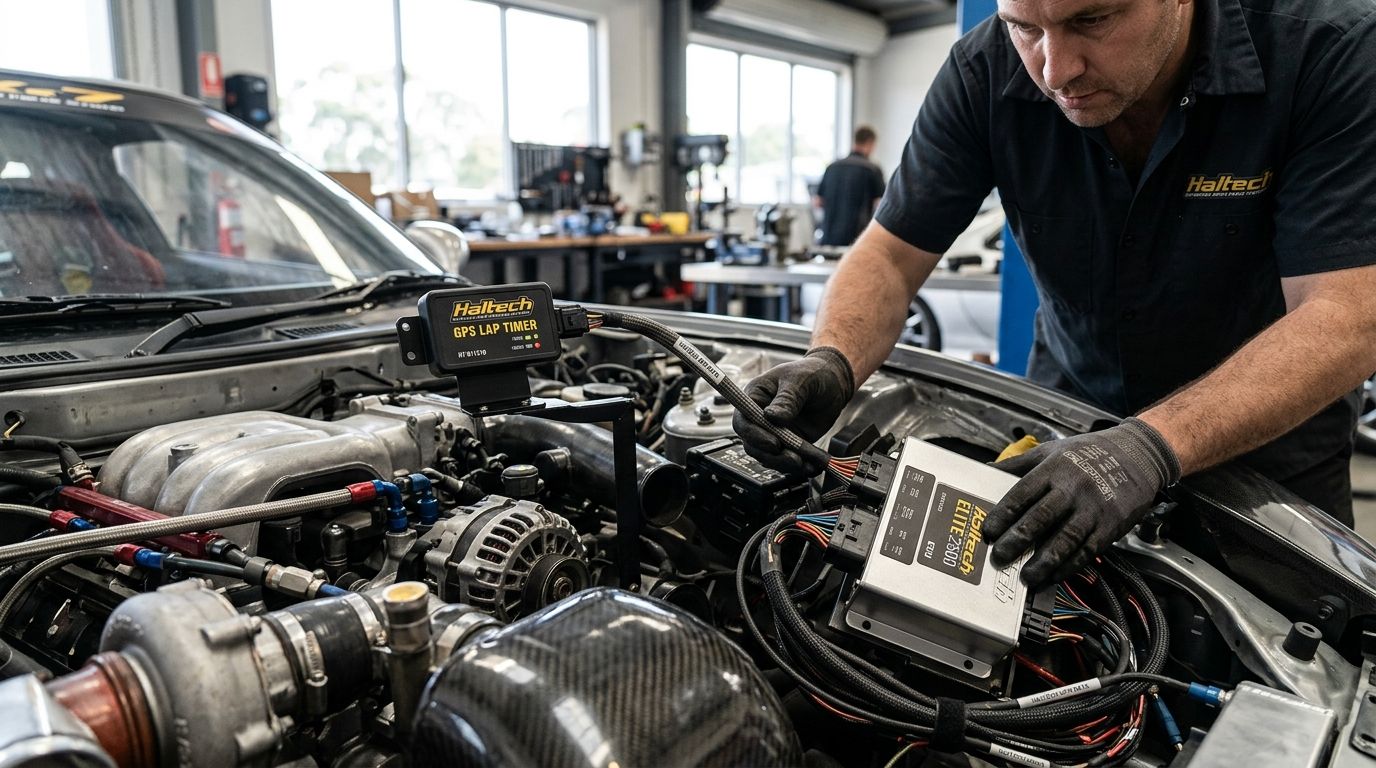
Once the base traction control setup is logging cleanly, there's more to build on top of it. Closed-loop fuel control can be layered in alongside slip management — see closed loop fuel tuning with a Haltech WBC1 for wiring an aftermarket wideband into the same ECU. Boost can also be scheduled per gear so power delivery matches available traction as the car accelerates through the box, covered in automatically control boost by gear with a Haltech Elite ECU. For circuit work, a GPS lap timer connected to the Haltech ECU lets you correlate traction control intervention with lap time directly, rather than guessing whether a tighter slip target actually helped.
FAQ
What does a haltech traction control setup actually need at minimum?
A haltech traction control setup needs at least two wheel speed sensor inputs (driven wheels) wired to spare digital inputs on the Haltech Elite ECU, plus a confirmed tone ring tooth count. Four sensors, covering both driven and non-driven wheels, give more accurate slip detection than a two-sensor setup.
Can traction control be added to any Haltech ECU?
Traction control as a dedicated function block is available on Haltech Elite series ECUs running current ESP software in 2026. Older or entry-level Haltech platforms may not carry the full function block, so check the specific ECU model's feature set before planning the build.
Which cut method should I start with, ignition cut or ignition retard?
Ignition retard gives a smoother, less abrupt reduction in power and suits most street and track-day setups as a starting point. Ignition cut reacts harder and faster, and is better reserved for launch control or severe slip events once the base tune is proven.
Do I need a crank trigger kit before setting up traction control?
Yes, the Haltech ECU needs a functioning crank trigger and cam sync signal before any function block, including traction control, can run reliably. Confirm crank trigger wiring and sensor gap first, then move on to wheel speed sensor configuration.
Why does traction control cut power when the tyres aren't actually spinning?
A false cut almost always traces back to an incorrect tone ring tooth count entered in the ESP software, which inflates the calculated slip figure. Recheck the tooth count against the physical trigger wheel on every wheel speed input before adjusting any other setting.
Is traction control the same as launch control on a Haltech ECU?
No, they are two separate function blocks that share the same wheel speed sensor inputs. Traction control manages rolling slip mid-corner, while launch control uses a different, more permissive slip target for standing starts.
How many wheel speed sensors does a proper setup use?
Four wheel speed sensors, one per corner, give the ECU both driven and non-driven reference speeds for the most accurate slip calculation. A two-sensor setup on the driven axle alone still works but loses some accuracy compared to a full four-corner install.
Can traction control be tuned without a dyno?
Yes, traction control tuning is normally done through on-track or on-road datalogging rather than on a dyno, since the function depends on wheel speed differential under real cornering and acceleration loads. Start conservative and refine the slip target and cut aggression from logged sessions.
One last thing
The most common mistake isn't the traction control tune itself, it's skipping the wheel speed sensor validation step on the hoist before the first drive — a five-minute check that catches a wrong tooth count before it costs a set of tyres or worse. Confirm all four corners read matching, sensible speeds by hand-spinning the wheels before the car ever leaves the workshop.