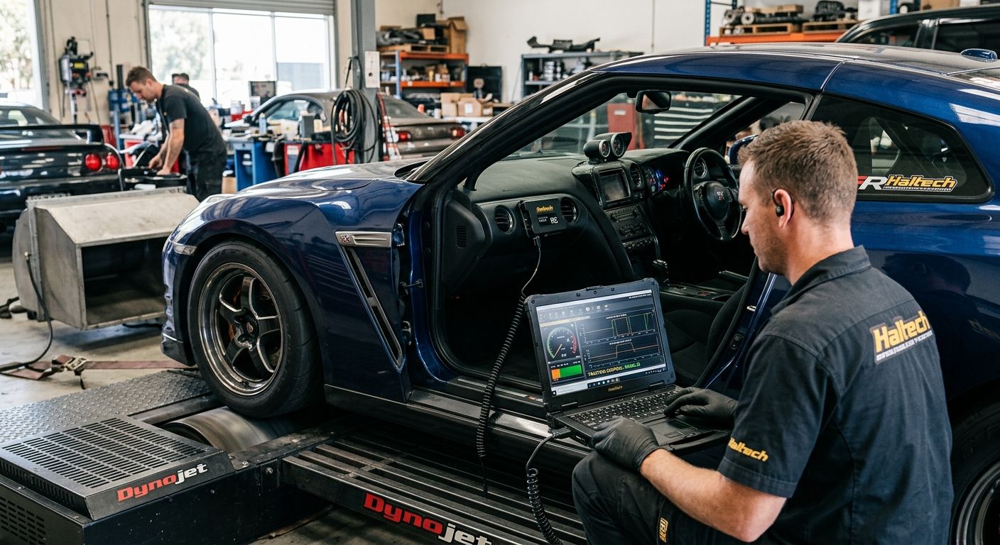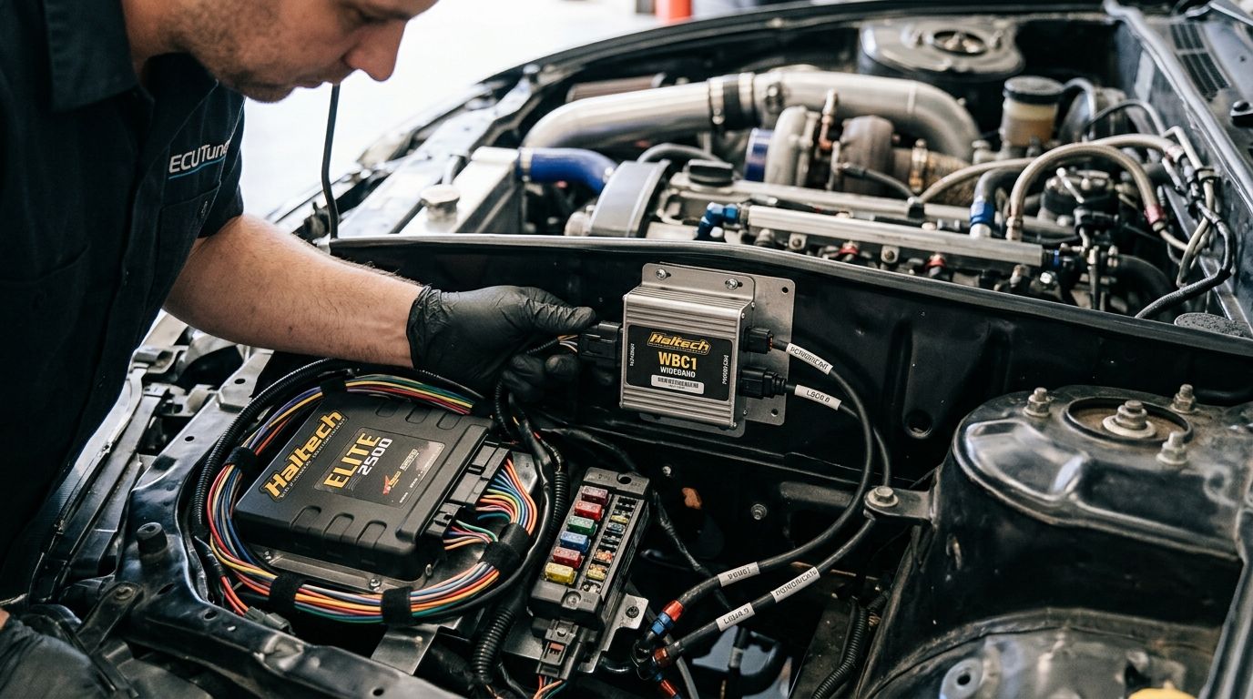
Running a wideband off a cheap analog gauge tells you the air-fuel ratio right now — it does not log data, does not talk to your ECU, and does not let the ECU correct fuelling in real time. Wire a Haltech WBC1 wideband controller into the ECU over CAN Bus instead, and the ECU sees live AFR as a native channel it can log, display and use for closed-loop fuel trim.
- Haltech WBC1 wideband controller connects to Elite, Nexus and PS-series ECUs over CAN Bus for a native AFR channel.
- Non-Haltech ECUs can still use the WBC1 through its 0-5V analog output if there's no CAN Bus input available.
- Sensor placement and CAN termination are the two setup steps that cause the most comebacks in 2026 wideband installs.
- Closed-loop fuel trim only works once the WBC1's AFR channel is assigned correctly inside the Haltech ECU software.
Why this matters
A narrowband O2 sensor only tells you rich or lean of 14.7:1 — useless for tuning a boosted engine that needs 11.5-12.5:1 under load. The Haltech WBC1 wideband controller reads a Bosch LSU 4.9 wideband sensor across the full AFR range and pushes that data onto the CAN Bus in real time.
Once the ECU has a live wideband channel, it can run closed-loop fuel trim at cruise and part-throttle, flag AFR faults, and log every run for post-drive analysis. That's the difference between tuning by feel and tuning with data — and it's the setup step most street-tuned Haltech cars in 2026 are still missing.
The wiring itself is short. The Haltech ECU platform you're running, the sensor location and the CAN Bus termination are what decide whether the install works first try or throws intermittent faults for a week.
Before you start
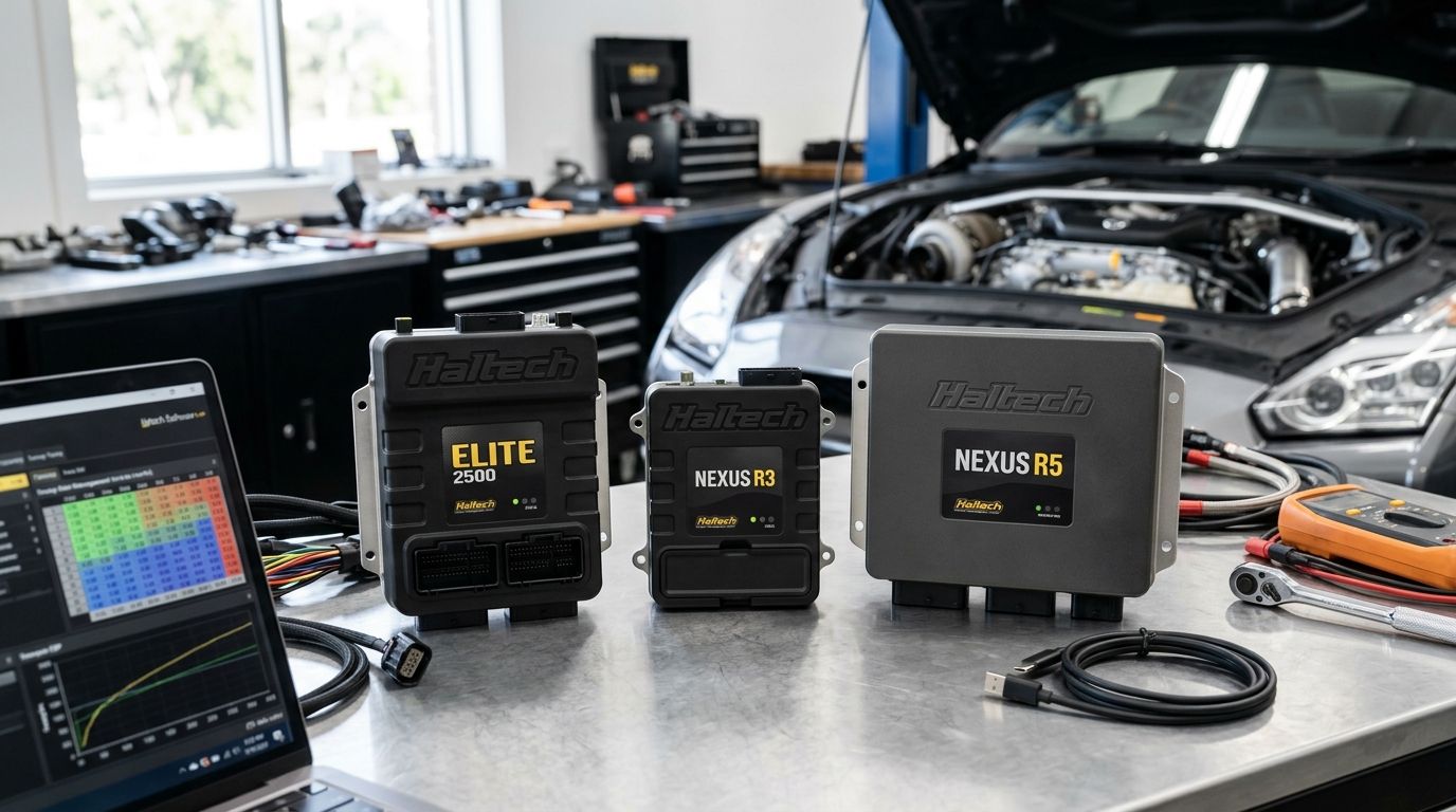
- A Haltech ECU with a CAN Bus input — Elite series, Nexus R5/R3, or PS1000/PS2000 all support native WBC1 integration. Older or non-Haltech ECUs need the analog output path instead (covered below).
- A Bosch LSU 4.9 wideband oxygen sensor and matching weld-in bung, positioned in the exhaust ahead of any catalytic converter, with enough clearance from the turbo to avoid a false lean reading from turbulent flow.
- A switched 12V feed with its own fuse, a clean chassis ground, and CAN Bus wiring (twisted pair, CAN H/CAN L) run to the ECU's CAN connector.
- The gotcha: the LSU 4.9 sensor heater pulls a real current spike on cold start. Tap power from an already-loaded circuit and you'll get a heater fault or a blown fuse the first cold morning you start the car — run the WBC1 on its own fused feed, not off an accessory circuit shared with fuel pumps or fans.
Set up the sensor and controller
- Weld the sensor bung into the exhaust at a slight upward angle so condensation drains away from the sensor tip, in a straight section of pipe rather than right off a merge collector.
- Mount the WBC1 controller body in a dry, vibration-isolated spot in the engine bay — away from headers and turbo heat soak.
- Plug the wideband sensor connector into the WBC1's sensor input. It only fits one way; don't force it.
- Run the sensor cable clear of the exhaust and any moving components, securing it every 150-200mm.
Expected result: the WBC1 powers up and begins its sensor heater warm-up cycle the moment ignition power is applied, with no error LED.
Wire power, ground and CAN Bus
- Connect the WBC1's power pin to your fused switched 12V feed and its ground pin to a clean chassis ground — not a ground shared with the ECU's sensor ground network.
- Connect CAN H and CAN L from the WBC1 into the same CAN Bus segment as the Haltech ECU.
- Confirm CAN Bus termination: a 120-ohm resistor at each physical end of the bus, and only at the two ends — not at every device.
- Power the system up and check for a stable CAN connection with no bus errors before moving into software.
Expected result: the ECU's CAN diagnostics show the WBC1 as an active device with no bus-off or error-passive flags.
Configure the WBC1 in the ECU software
- Open the Haltech ECU tuning software and go into the CAN device setup screen.
- Add the Haltech WBC1 as a CAN device from the device list — the ECU auto-detects the correct broadcast frame if wiring is correct.
- Assign the WBC1's AFR output to an available Analog Value channel or the dedicated wideband channel, depending on your ECU firmware version.
- Set the fuel type (petrol, E85, etc.) so the ECU converts the sensor's lambda output into the correct AFR number for that fuel.
- Save and go online to confirm the AFR channel is streaming live data that matches ambient air conditions before start-up (typically reads near 14.7:1 with no engine running, since the sensor is exposed to atmospheric oxygen).
Expected result: a live, updating AFR value on the ECU dash or logging screen that tracks with throttle input the moment the engine starts.
Wiring a WBC1 to a non-Haltech ECU
Running a standalone or aftermarket ECU without a CAN Bus input? The WBC1 still works — you lose the plug-and-play CAN integration and use its 0-5V analog output instead.
- Wire the WBC1's analog output pin to a spare analog voltage input on your ECU.
- Wire power and ground exactly as per the CAN setup above — the sensor and heater circuit don't change.
- In your ECU's software, set up a custom analog channel and enter the WBC1's voltage-to-AFR calibration table from the Haltech WBC1 documentation.
- Confirm the channel reads correctly at idle against a second reference wideband if one is available, since analog scaling errors are the most common mistake on this path.
Expected result: an AFR value on your non-Haltech dash or logging software that moves in step with throttle and boost changes, same as the native CAN setup.
“An AFR channel that only updates at idle and freezes under boost is a wiring problem, not a tuning problem.”
Troubleshooting
- ECU doesn't detect the WBC1 on CAN Bus — check CAN H/CAN L aren't swapped and confirm 120-ohm termination at both bus ends, not zero or double termination.
- AFR reads lean immediately after cold start, then settles — normal. The sensor needs its warm-up cycle to complete before readings stabilise; don't tune off data from the first 20-30 seconds.
- AFR jumps around erratically at idle — almost always an exhaust leak upstream of the sensor pulling in outside air, not a faulty WBC1.
- Heater fault or blown fuse on cold start — the WBC1 is sharing a circuit with another high-draw accessory. Move it to its own fused feed.
- Analog channel on a non-Haltech ECU reads flat or maxed out — the voltage-to-AFR scaling table is wrong or the wire is on the wrong input pin type (check it's a true analog input, not digital).
Customise your workflow
Once the WBC1 is streaming a clean AFR channel, put it somewhere you'll actually watch it. The Haltech IC-7 dash displays live AFR alongside boost and knock on a single screen for track days and street driving, so you're not scrolling through the tuning laptop mid-run.
If you're building the wideband install as part of a bigger six-cylinder turbo project, the wiring and ECU choice matter well before the WBC1 goes in — see the Haltech ECU setup for turbocharged six-cylinder builds for platform-specific guidance. Platforms like the RB30 covered in the RB30 engine build guide are common candidates for this exact WBC1-plus-Elite ECU setup.
Sourcing a WBC1 or Haltech ECU?
Spool Imports stocks Haltech wideband controllers and ECU packages for six-cylinder and V8 builds.
FAQ
What sensor does the Haltech WBC1 use?
The Haltech WBC1 wideband controller is built around the Bosch LSU 4.9 wideband oxygen sensor, which reads air-fuel ratio across the full range rather than just rich-or-lean like a narrowband sensor.
Can the WBC1 work with a non-Haltech ECU?
Yes. The WBC1 outputs a 0-5V analog signal alongside its CAN Bus output, so any ECU with a spare analog input can read AFR once you enter the correct voltage-to-AFR scaling in that ECU's software.
Where should the wideband sensor bung be welded?
Weld the bung into a straight section of exhaust pipe ahead of any catalytic converter, angled slightly upward so condensation drains away from the sensor tip rather than pooling against it.
Why does my WBC1 read lean right after cold start?
This is normal sensor warm-up behaviour. The LSU 4.9 sensor needs a short heating cycle before its readings stabilise, so ignore AFR data from the first 20-30 seconds after startup.
How many CAN Bus termination resistors does a WBC1 install need?
Two 120-ohm resistors total, one at each physical end of the CAN Bus segment. Adding termination at every device or skipping it entirely causes intermittent CAN dropouts.
Does the WBC1 let the ECU run closed-loop fuel trim?
Yes, once the WBC1's AFR channel is correctly assigned in the Haltech ECU software the ECU can use that live AFR data to trim fuel automatically at cruise and part-throttle.
Why is my AFR reading unstable at idle?
An erratic idle AFR reading is almost always an exhaust leak upstream of the sensor pulling in outside air, not a fault with the WBC1 itself.
Can one WBC1 run two wideband sensors?
No, the WBC1 is a single-channel controller — a twin-turbo or V-configuration engine tuning per-bank AFR needs a second WBC1 unit and its own CAN device assignment.
One last thing
Most WBC1 comebacks in 2026 aren't sensor faults — they're CAN termination or shared-circuit power problems that show up as intermittent AFR dropouts weeks after the install, long after the installer has moved on to the next job. Wire the heater circuit on its own fuse and get termination right the first time, and the WBC1 will run without another look for years.